
קובץ:Ebers-Moll model schematic (NPN).svg

גודל התצוגה המקדימה הזאת מסוג PNG של קובץ ה־SVG הזה: 250 × 175 פיקסלים. רזולוציות אחרות: 320 × 224 פיקסלים | 640 × 448 פיקסלים | 1,024 × 717 פיקסלים | 1,280 × 896 פיקסלים | 2,560 × 1,792 פיקסלים.
לקובץ המקורי (קובץ SVG, הגודל המקורי: 250 × 175 פיקסלים, גודל הקובץ: 65 ק"ב)
| זהו קובץ שמקורו במיזם ויקישיתוף. תיאורו בדף תיאור הקובץ המקורי (בעברית) מוצג למטה. |
.svg)
.svg?uselang=he)
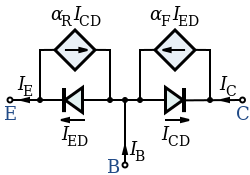
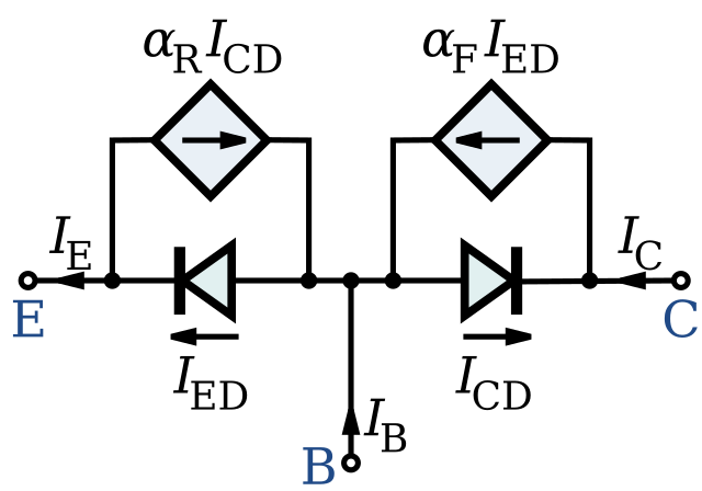
| תיאור | A schematic diagram of the Ebers-Moll models of an NPN BJT. The base, collector and emitter currents are IB, IC and IE, the common-base forward and reverse current gains are αF and αR, and the collector and emitter diode currents are ICD and IED. |
| תאריך יצירה | (UTC) |
| מקור | |
| יוצר |
|
הקובץ הזה מתפרסם לפי תנאי רישיון קריאייטיב קומונז ייחוס-שיתוף זהה 3.0 לא מותאם.
- הנכם רשאים:
- לשתף – להעתיק, להפיץ ולהעביר את העבודה
- לערבב בין עבודות – להתאים את העבודה
- תחת התנאים הבאים:
- ייחוס – יש לתת ייחוס הולם, לתת קישור לרישיון, ולציין אם נעשו שינויים. אפשר לעשות את זה בכל צורה סבירה, אבל לא בשום צורה שמשתמע ממנה שמעניק הרישיון תומך בך או בשימוש שלך.
- שיתוף זהה – אם תיצרו רמיקס, תשנו, או תבנו על החומר, חובה עליכם להפיץ את התרומות שלך לפי תנאי רישיון זהה או תואם למקור.
יומן העלאה מקורי
This image is a derivative work of the following images:
- File:Ebers-Moll_Model_NPN.PNG licensed with Cc-by-sa-3.0-migrated-with-disclaimers, GFDL-en
- 2010-03-28T19:03:03Z CosineKitty 527x254 (13194 Bytes) Removed incorrect "+" and "-" symbols: charge carriers were backwards for NPN.
- 2010-03-28T18:44:20Z CosineKitty 527x254 (14276 Bytes) Made the following changes to fix errors in the diagram. These changes are based on the diagram on page 903 in ''Microelectronic Circuits, second edition'' by Adel S. Sedra and Kenneth C. Smith, ISBN 0-03-007328-6. 1. Revers
- 2007-09-16T00:43:26Z Kved 527x254 (10811 Bytes) {{Information |Description=NOTE: The diagram has an error. The current through the Base-to-Collector diode should be ICD, not IED. == Summary == Drawn using "Klunky" and added the minor details using MS-WORD |Source=Originall
Uploaded with derivativeFX
היסטוריית הקובץ
ניתן ללחוץ על תאריך/שעה כדי לראות את הקובץ כפי שנראה באותו זמן.
| תאריך/שעה | תמונה ממוזערת | ממדים | משתמש | הערה | |
|---|---|---|---|---|---|
| נוכחית | 07:24, 28 באוקטובר 2011 | | 175 × 250 (65 ק"ב) | Ea91b3dd | Corrected the labels on the dependent current sources. They current I subscripts were swapped. |
| 07:48, 4 באוגוסט 2010 |  | 175 × 250 (31 ק"ב) | Inductiveload | {{Information |Description=A schematic diagram of the Ebers-Moll models of an NPN BJT. The base, collector and emitter currents are ''I''<sub>B</sub>, ''I''<sub>C</sub> and ''I''<sub>E</sub>, the common-base forward and reverse current gains are ''α''<su |
שימוש בקובץ
הדף הבא משתמש בקובץ הזה:
שימוש גלובלי בקובץ
אתרי הוויקי השונים הבאים משתמשים בקובץ זה:
- שימוש באתר ar.wikipedia.org
- שימוש באתר en.wikipedia.org
- שימוש באתר fr.wikibooks.org
- שימוש באתר uk.wikipedia.org
- שימוש באתר zh.wikipedia.org
.svg)